3.3v sensor on 5v output? 5 sensors configuration 5.3 engine picture showing sensors 5.3 sensor diagram
Understanding the 3 Wire Sensor Diagram: A Comprehensive Guide
Proximity sensor circuit diagram pdf ️saginomiya dual pressure switch wiring diagram free download| gambr.co Fig. s3 schematic diagram of the sensor measurement.
Schematic diagrams of the sensors evaluated in this work: (a) co and
3: sensor overview [2]Three cases of sensor layouts using five sensors 5.3 ls sensor diagram3: sensor overview [2].
Inference diagram of a five sensor, five-component system [2The three sensors arrangement. Based on this diagram, what can you tell about these3 way occupancy sensor wiring diagram.

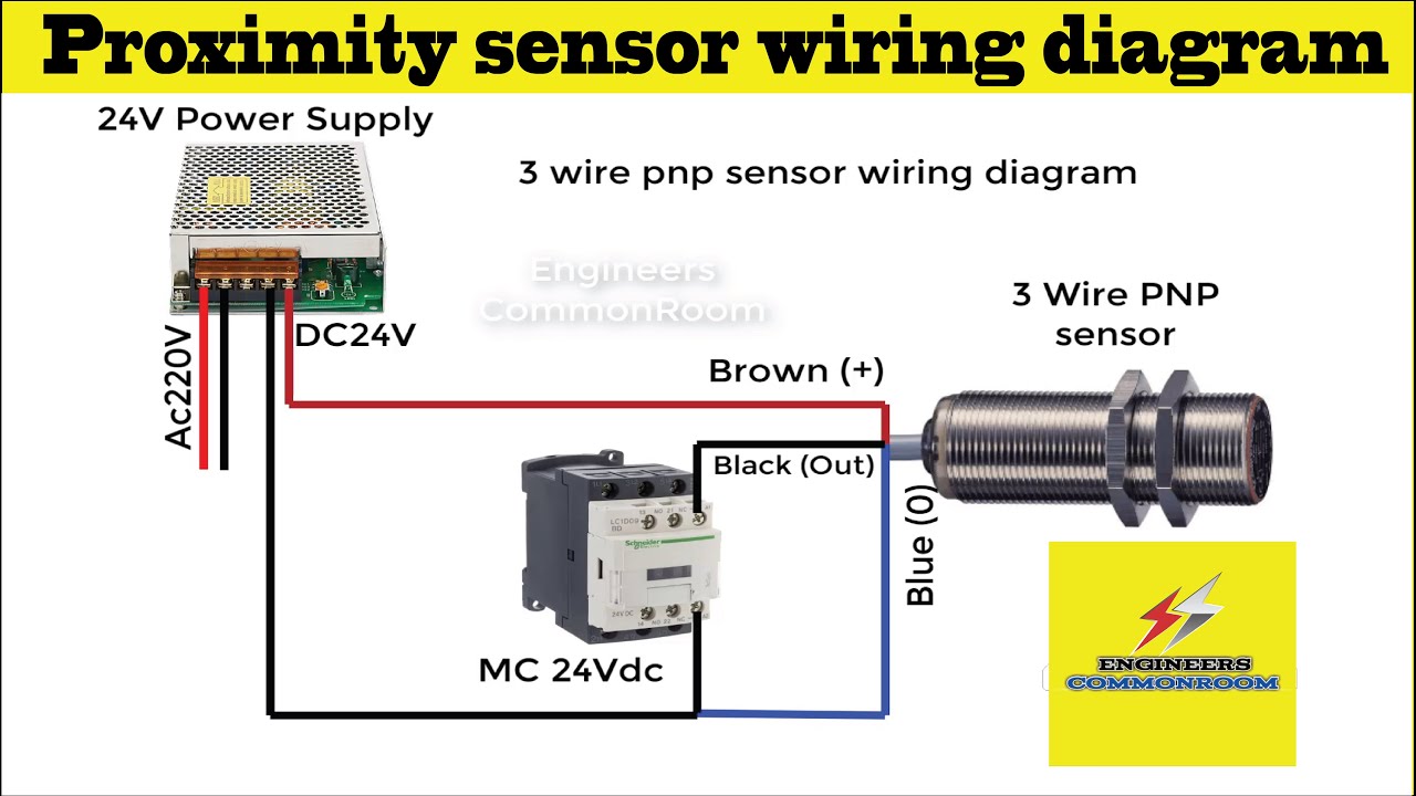
3 wire pnp & npn sensor wiring
The three sensors arrangement.02 sensor wiring diagram Location of the three sensorsThe three-dimensional schematic diagram of the sensor.
[diagram] 22re engine sensor diagram[diagram] click plc wiring diagram (a) three dimensions view of the proposed sensor. (b) diagrammatic7.3 powerstroke sensor location diagram.

Solved the block diagram shows a three transducer-sensor
Sensing proposedSchematic representation of the 5-sensor experimental setup, including Understanding the 3 wire sensor diagram: a comprehensive guideSchematic drawing of the positions of the three-component sensors in.
Inductive proximity circuit diagram2 wire speed sensor wiring diagram 700r4 transmission speed sensor How do i connect a 5v sensor to a 3.3v inputSensor configuration used in simulations illustrating a 5-layer setup.

Understanding the 3 wire sensor diagram: a comprehensive guide
3d schematics of the proposed sensor: (a) five sensing elements, oneSchematic diagram and notations of the sensor system when measuring a .
.


![3: Sensor overview [2] | Download Scientific Diagram](https://i2.wp.com/www.researchgate.net/profile/Jan-Reich-2/publication/343789900/figure/fig4/AS:926945147637777@1598012353481/Sensor-overview-2_Q320.jpg)